
VIP member
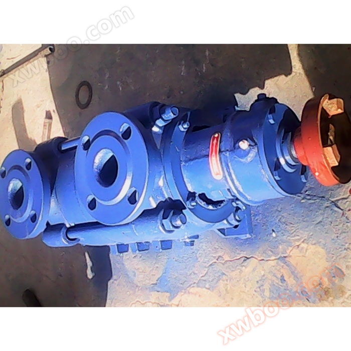
GC horizontal multi-stage boiler feed pump
Release time: 2015-5-21 10:17:17 Brand: Longyang Pump Valve model: GC series Flow rate: 5~55m ³/h Head: 46~301m Power: 3~75KW Speed: 2950r/min Caliber
Product details
1 Overview of GC horizontal multi-stage boiler feed pump products
GC type pump is a horizontal, single suction multi-stage, segmented centrifugal pump. It has the characteristics of high efficiency, wide performance range, safe and stable operation, low noise, long service life, and easy installation and maintenance. Used for transporting clean water or other liquids with physical and chemical properties similar to water.
2 All of our products are designed and optimized using computers. Our company has strong technical strength, rich production experience, and comprehensive testing methods to ensure stable and reliable product quality.

3 The significance of GC horizontal multi-stage boiler feed pump model
Application of GC horizontal multi-stage boiler feed pump product
4 The GC type horizontal multi-stage boiler feed pump is suitable for industrial and urban water supply and drainage, high-rise building pressurized water supply, garden sprinkler irrigation, fire boosting, long-distance water supply, heating, bathroom and other cold and warm water circulation boosting and equipment matching, especially suitable for small boiler feed water.
Main characteristics of GC horizontal multi-stage boiler feed pump
1. The hydraulic model is advanced, efficient, and has a wide range of performance.
2. The pump runs smoothly with low noise.
1. The hydraulic model is advanced, efficient, and has a wide range of performance.
2. The pump runs smoothly with low noise.
5 3. The shaft seal adopts soft packing sealing, which is safe, reliable, structurally simple, and easy to maintain.

Structure diagram of GC horizontal multi-stage boiler feed pump
1. The GC type water pump is a multi-stage segmented design, with the inlet and outlet of the 1.5GC-4GC models located on the inlet and outlet sections respectively, all vertically upward. The head of the water pump can be increased or decreased according to usage needs. Whether the water pump is well assembled or not has a great impact on its performance, especially the relative position between the outlet of each impeller and the inlet of the guide vane. The center of the outlet of each suction impeller must be aligned with the center of the guide vane. Any slight deviation will reduce the flow rate, head, and efficiency of the water pump. Therefore, it is necessary to pay attention to assembly after maintenance, and adjust if there is any deviation.
2. The main components of GC type water pump include shaft, shaft sleeve, inlet section, impeller, guide wing, sealing ring, middle section, outlet section, balance ring, balance plate, tail cover inlet section, middle section, and outlet section cover, all of which are made of cast iron, forming the working chamber of the pump.
3. The impeller is made of cast iron and has blades inside. The liquid enters on one side along the axial direction. Due to the unequal pressure on the impeller before and after, there must be an axial force, which is borne by the balance plate. The impeller is manufactured through static balance testing.
4. The shaft is made of high-quality carbon steel, with an impeller installed in the middle, fixed on the shaft with keys, shaft sleeves, and shaft sleeve nuts. One end of the shaft is equipped with a coupling component and directly connected to the motor. When viewed from the direction of rotation, the pump shaft rotates clockwise.
5. Is the sealing ring cast? Made to prevent high-pressure water from leaking back into the inlet section of the water pump, it is fixed in the inlet and middle sections respectively. It is a vulnerable part and can be replaced with spare parts after wear and tear.
6. The balance ring is made of cast iron and fixed on the outlet section. It, together with the balance plate, forms the balance device. The balance plate is made of wear-resistant cast iron and is installed on the shaft, located between the 7th and 7th sections and the tail cover, to balance axial forces. The shaft sleeve is made of cast iron and located at the two packing chambers, used to fix the impeller and protect the pump shaft. For vulnerable parts, they can be replaced with spare parts after wear and tear.
7. The bearing is a single row radial ball bearing lubricated with calcium based grease. The packing plays a sealing role, preventing air from entering and a large amount of liquid from leaking out.
6 8. The packing seal consists of a packing chamber on the inlet section and tail cover, a packing gland, a packing ring, and packing, etc. A small amount of high-pressure water flows into the packing chamber to provide a water seal. The tightness of the filler must be appropriate, neither too tight nor too loose, based on the liquid being able to seep out drop by drop. If the packing is too tight, the shaft sleeve is prone to heating and consuming power. The packing is too loose, which reduces the efficiency of the water pump due to liquid loss.
| Performance parameters of GC horizontal multi-stage boiler feed pump | model traffic |
(m³/h) head |
(m) speed |
(r/min) efficiency |
(%) | |
| Power (kW) | shaft power | |||||
| Motor power | 6 | 46 | 2950 | 38 | 2 | 3 |
| 1.5GC-5×2 | 6 | 69 | 2950 | 38 | 3 | 4 |
| 1.5GC-5×3 | 6 | 92 | 2950 | 38 | 4 | 5.5 |
| 1.5GC-5×4 | 6 | 115 | 2950 | 38 | 5 | 7.5 |
| 1.5GC-5×5 | 6 | 138 | 2950 | 38 | 6 | 7.5 |
| 1.5GC-5×6 | 6 | 161 | 2950 | 38 | 7 | 7.5 |
| 1.5GC-5×7 | 6 | 184 | 2950 | 38 | 8 | 11 |
| 1.5GC-5×8 | 6 | 207 | 2950 | 38 | 9 | 11 |
| 1.5GC-5×9 | 10 | 64 | 2950 | 39.6 | 4.4 | 7.5 |
| 2GC-5×2 | 10 | 96 | 2950 | 39.6 | 6.6 |
11.0
|
| 2GC-5×3 | 10 | 128 | 2950 | 39.6 | 8.8 | 15.0 |
| 2GC-5×4 | 10 | 160 | 2950 | 39.6 | 11.0 | 15.0 |
| 2GC-5×5 | 10 | 192 | 2950 | 39.6 | 13.2 | 18.5 |
| 2GC-5×6 | 10 | 224 | 2950 | 39.6 | 15.4 | 22.0 |
| 2GC-5×7 | 10 | 256 | 2950 | 39.6 | 17.6 | 30.0 |
| 2GC-5×8 | 10 | 288 | 2950 | 39.6 | 19.8 | 30.0 |
| 2GC-5×9 | 15 | 62 | 2950 | 43.7 | 5.8 | 11.0 |
| 20 | 54 | 2950 | 47.4 | 6.2 | 11.0 | |
| 2.5GC-6×2 | 15 | 93 | 2950 | 43.7 | 8.7 | 15.0 |
| 20 | 81 | 2950 | 47.4 | 9.3 | 15.0 | |
| 2.5GC-6×3 | 15 | 124 | 2950 | 43.7 | 11.6 | 22.0 |
| 20 | 108 | 2950 | 47.4 | 12.4 | 22.0 | |
| 2.5GC-6×4 | 15 | 155 | 2950 | 43.7 | 14.5 | 22.0 |
| 20 | 135 | 2950 | 47.4 | 15.5 | 22.0 | |
| 2.5GC-6×5 | 15 | 186 | 2950 | 43.7 | 17.4 | 30.0 |
| 20 | 162 | 2950 | 47.4 | 18.6 | 30.0 | |
| 2.5GC-6×6 | 15 | 217 | 2950 | 43.7 | 20.2 | 30.0 |
| 20 | 189 | 2950 | 47.4 | 21.7 | 30.0 | |
| 2.5GC-6×7 | 15 | 248 | 2950 | 43.7 | 23.2 | 37.0 |
| 20 | 216 | 2950 | 47.4 | 24.8 | 37.0 | |
| 2.5GC-6×8 | 15 | 279 | 2950 | 43.7 | 26.1 | 22 |
| 20 | 243 | 2950 | 47.4 | 27.9 | 22 | |
| 2.5GC-6×9 | 30 | 86 | 2950 | 51 | 13.8 | 30 |
| 45 | 82 | 2950 | 60 | 16.8 | 30 | |
| 55 | 76 | 2950 | 62.5 | 18.1 | 30 | |
| 4GC-8×2 | 30 | 129 | 2950 | 51 | 20.7 | 37 |
| 45 | 123 | 2950 | 60 | 25.2 | 37 | |
| 55 | 114 | 2950 | 62.5 | 27.2 | 37 | |
| 4GC-8×3 | 30 | 172 | 2950 | 51 | 27.6 | 55 |
| 45 | 164 | 2950 | 60 | 27.6 | 55 | |
| 55 | 152 | 2950 | 62.5 | 36.2 | 55 | |
| 4GC-8×4 | 30 | 215 | 2950 | 51 | 34.5 | 55 |
| 45 | 205 | 2950 | 60 | 42.0 | 55 | |
| 55 | 190 | 2950 | 62.5 | 45.3 | 55 | |
| 4GC-8×5 | 30 | 258 | 2950 | 51 | 41.4 | 75 |
| 45 | 246 | 2950 | 60 | 50.4 | 75 | |
| 55 | 228 | 2950 | 62.5 | 54.1 | 75 | |
| 4GC-8×6 | 30 | 301 | 2950 | 51 | 48.2 | 75 |
| 45 | 287 | 2950 | 60 | 58.8 | 75 | |
| 55 | 266 | 2950 | 62.5 | 63.4 | 75 | |
| 4GC-8×7 | 30 | 344 | 2950 | 51 | 55.0 | 100 |
| 45 | 328 | 2950 | 60 | 67.0 | 100 | |
| 55 | 304 | 2950 | 62.5 | 73.0 | 100 | |
| 4GC-8×8 | 30 | 387 | 2950 | 51 | 62.0 | 100 |
| 45 | 369 | 2950 | 60 | 75.5 | 100 | |
| 55 | 342 | 2950 | 62.5 | 82.0 | 100 | |
| 4GC-8×9 | 30 | 430 | 2950 | 51 | 69.0 | 4GC-8×10 |
| 45 | 410 | 2950 | 60 | 84.0 | - | |
| 55 | 380 | 2950 | 62.5 | 91.0 | - | |
7 -
Installation dimensions of GC horizontal multi-stage boiler feed pump
1.5GC-5
8-Φ18

| Outline dimension table | model | series | ||||||||||||||||||
| size | A | B | C | D | E | F | G | H | I | J | K | L | M | |||||||
| N | 2 | 576 | 227.5 | 166 | 247.5 | 120 | 50 | 248 | 122.5 | 135 | 150 | 165 | 220 | 175 | 50 | |||||
| 3 | 626 | 227.5 | 210 | 247.5 | 170 | 50 | 248 | 172.5 | 135 | 150 | 165 | 220 | 175 | 50 | ||||||
| 4 | 676 | 227.5 | 260 | 247.5 | 220 | 50 | 248 | 222.5 | 135 | 150 | 165 | 220 | 175 | 50 | ||||||
| 5 | 726 | 227.5 | 310 | 247.5 | 270 | 50 | 248 | 272.5 | 135 | 150 | 165 | 220 | 175 | 50 | ||||||
| 6 | 776 | 227.5 | 360 | 247.5 | 320 | 50 | 248 | 322.5 | 135 | 150 | 165 | 220 | 175 | 50 | ||||||
| 7 | 826 | 227.5 | 410 | 247.5 | 370 | 50 | 248 | 372.5 | 135 | 150 | 165 | 220 | 175 | 50 | ||||||
| 8 | 876 | 227.5 | 460 | 247.5 | 420 | 50 | 248 | 422.5 | 135 | 150 | 165 | 220 | 175 | 50 | ||||||
| 9 | 926 | 227.5 | 510 | 247.5 | 470 | 50 | 248 | 472.5 | 135 | 150 | 165 | 220 | 175 | 50 | ||||||
|
|
||||||||||||||||||||
| 1.5GC-5 | model | series | ||||||||||||||||||
| size | A | B | C | D | E | F | G | H | I | J | K | L | M | |||||||
| N | 2 | 740 | 290 | 210 | 315 | 160 | 70 | 325 | 160 | 180 | 220 | 210 | 320 | 270 | 75 | |||||
| 3 | 800 | 290 | 270 | 315 | 220 | 70 | 325 | 220 | 180 | 220 | 210 | 320 | 270 | 75 | ||||||
| 4 | 860 | 290 | 330 | 315 | 280 | 70 | 325 | 280 | 180 | 220 | 210 | 320 | 270 | 75 | ||||||
| 5 | 920 | 290 | 390 | 315 | 340 | 70 | 325 | 340 | 180 | 220 | 210 | 320 | 270 | 75 | ||||||
| 6 | 980 | 290 | 450 | 315 | 400 | 70 | 325 | 400 | 180 | 220 | 210 | 320 | 270 | 75 | ||||||
| 7 | 1040 | 290 | 510 | 315 | 460 | 70 | 325 | 460 | 180 | 220 | 210 | 320 | 270 | 75 | ||||||
| 8 | 1100 | 290 | 570 | 315 | 520 | 70 | 325 | 520 | 180 | 220 | 210 | 320 | 270 | 75 | ||||||
| 9 | 1160 | 290 | 630 | 315 | 580 | 70 | 325 | 580 | 180 | 220 | 210 | 320 | 270 | 75 | ||||||

|
Dimensional drawing of suction and discharge flange model |
size | |||
| Inlet and outlet flange size | D | O | a | ||
| n-d | 40 | 110 | 145 | 1.5GC | |
| 4-Φ18 | 50 | 125 | 160 | 2GC | |
| 4-Φ18 | 65 | 145 | 180 | 2.5GC | |

| 2.5GC-3.5, 4GC Outline Dimensional Drawing | model | series | |||||||||||||
| size | A | B | C | D | E | F | G | H | I | J | K | L | M | ||
| N | 2 | 879 | 320 | 320 | 355 | 250 | 85 | 385 | 190 | 215 | 285 | 240 | 420 | 340 | 85 |
| 3 | 945 | 320 | 395 | 355 | 325 | 85 | 385 | 265 | 215 | 285 | 240 | 420 | 340 | 85 | |
| 4 | 1020 | 320 | 470 | 355 | 400 | 85 | 385 | 340 | 215 | 285 | 240 | 420 | 340 | 85 | |
| 5 | 1095 | 320 | 545 | 355 | 475 | 85 | 385 | 415 | 215 | 285 | 240 | 420 | 340 | 85 | |
| 6 | 1170 | 320 | 620 | 355 | 550 | 85 | 385 | 490 | 215 | 285 | 240 | 420 | 340 | 85 | |
| 7 | 1245 | 320 | 695 | 355 | 625 | 85 | 385 | 265 | 215 | 285 | 240 | 420 | 340 | 85 | |

|
4GC
|
size | |||
| Inlet and outlet flange size | D | O | a | ||
| n-d | 100 | 190 | 230 | 4GC | |
Online inquiry
-
Contacts
-
Company
-
Telephone
-
Email
-
WeChat
-
Verification Code
-
Message Content
-