VIP member

2SK two-stage water ring vacuum pump
The 2SK two-stage water ring vacuum pump and the 2SK-P1 two-stage water ring vacuum pump atmospheric jet pump unit are used to extract air and other n
Product details
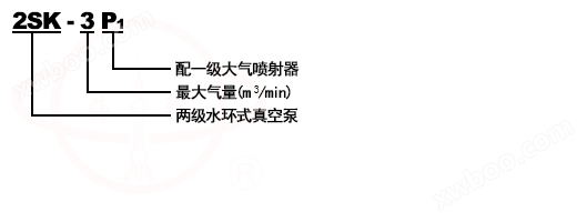
Model Meaning
Purpose and scope of use
The 2SK two-stage water ring vacuum pump and the 2SK-P1 two-stage water ring vacuum pump atmospheric jet pump unit are used to extract air and other non corrosive, water-insoluble, and solid particle free gases to achieve higher vacuum in closed containers.
The 2SK two-stage water ring vacuum pump is widely used in vacuum evaporation, vacuum concentration, vacuum rehydration, vacuum impregnation, vacuum drying, and vacuum smelting in the fields of food, weaving chemical, pharmaceutical, metallurgical industries, and electronics. It has the characteristics of high vacuum degree, high pumping speed in high vacuum zone, compact structure, reliable operation, and easy maintenance.
The 2SK type is suitable for working conditions where the suction pressure is below -0.08MPa. The 2SK-P1 series is suitable for working conditions where the suction pressure is below -0.096MPa. When equipped with an atmospheric pump, the ultimate vacuum degree can reach -750mmHg.
The working vacuum range is -0.03-0.08MPa.
working principle
| The working principle of the 2SK two-stage water ring vacuum pump is shown in Figure 1. The impeller (5) is eccentrically installed inside the pump body (3). When the impeller rotates, water is thrown out in all directions by centrifugal force, forming a rotating water ring (6) between the inner wall of the 2SK water ring vacuum pump body and the impeller. The upper inner surface of the water ring is in contact with the impeller hub. When the impeller rotates clockwise, during the first half of the rotation, the inner surface of the water ring gradually separates from the hub, and the cavity formed between adjacent blades gradually increases. The extracted gas is continuously sucked into the cavity through the pump inlet pipe (4) and the crescent shaped suction hole (7); During the second half of the rotation, the inner surface of the water ring gradually approaches the hub, and the cavity between the two adjacent blades gradually shrinks. The gas is compressed, so the pressure continues to increase. When the pressure increases to greater than the external pressure, the gas is discharged, continuously pumping away the gas in the sealed container, forming a certain vacuum. | ||
Figure 1: Schematic diagram of the working principle of 2SK two-stage water ring vacuum pump |
||
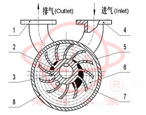 |
1 |
exhaust pipe |
2 |
vent hole |
|
3 |
pump body |
|
4 |
intake pipe |
|
5 |
impeller |
|
6 |
water ring |
|
7 |
air intake hole |
|
Structural Description
Figure 2 Structure diagram of two-stage water ring pump with pumping capacity of 1.5m3/min (2SK-1.5) or above |
||||
 |
1 |
Rear axle pressure cover |
12 |
oil cup |
2 |
axis |
13 |
front bearing cover |
|
3 |
Bearing frame |
14 |
gland |
|
4 |
Front and rear end caps |
15 |
Back Cover Garden Disk |
|
5 |
Short pump body |
16 |
Short impeller |
|
6 |
Middle wall (B) |
17 |
Long impeller |
|
7 |
Middle wall (A) |
18 |
Pump coupling |
|
8 |
Tension Bolt |
19 |
Motor coupling |
|
9 |
Long pump body |
20 |
bushing |
|
10 |
connected pipe |
21 |
Inlet hole |
|
11 |
Adjusting pad |
22 |
Front Cover Garden Plate |
|
| The structure of a 2SK two-stage water ring vacuum pump with a pumping capacity of 1.5m3/min or more is shown in Figure 2. The long and short impellers 17 and 16 are fixed to shaft 2 with keys, and the middle of the two impellers is positioned with a shaft sleeve 20 and locked with a round nut. This forms the entire rotor part, which is eccentrically installed in the pump body and supported on two single row radial ball bearings. The rotating part is connected to the motor shaft with a coupling 18 to rotate at the same speed as the motor. The long impeller 17, the long pump body 9, and the suction part form a high vacuum stage, while the short pump body 5, the short impeller 16, and the discharge part form a low vacuum stage. The exhaust port of the high vacuum stage is connected to the suction port of the low vacuum stage with a connecting pipe. 2SK-1.5 without this connecting pipe forms a two-stage series connection, separated by a middle wall (A) 7 and a middle wall (B) 6 between the two stages. The middle wall (A) has an exhaust hole, and the middle wall (B) has an intake port. | ||||
Product Features
1. Compared to the SK series single-stage water ring vacuum pump, it has the characteristics of high vacuum degree and high pumping speed in high vacuum areas.
2. At the same pumping rate, the shaft power is significantly higher than that of the 2BV and 2BE series water ring vacuum pumps.
3. Due to the double bladed wheel structure, manufacturing and maintenance are relatively complex, and there are many vulnerable parts.
technical specifications
model |
Extraction volume (m)3/min) |
ultimate pressure |
Power (kw) |
Rotational speed (r.p.m.) |
Water supply volume (L/min) |
Suction and exhaust diameter |
||
When the suction pressure is -0.093MPa, it shall not be less than |
MmHg |
MPa |
||||||
2SK-1.5 |
1.5 |
0.9 |
-730 |
-0.097 |
4 |
1440 |
10~15 |
φ40 |
2SK-3 |
3 |
2 |
-735 |
-0.098 |
7.5 |
1440 |
15~20 |
φ40 |
2SK-6 |
6 |
4 |
-735 |
-0.098 |
15 |
1460 |
25~35 |
φ70 |
2SK-12 |
12 |
8 |
-735 |
-0.098 |
22 |
970 |
40~50 |
φ100 |
2SK-30 |
20 |
14 |
-735 |
-0.098 |
45 |
740 |
60~80 |
φ125 |
2SK-30 |
30 |
20 |
-735 |
-0.098 |
55 |
740 |
70~90 |
φ125 |
Disassembly and assembly
(1) Dismantling of 2SK two-stage water ring vacuum pump:
The disassembly of 2SK two-stage water ring vacuum pump is divided into partial disassembly inspection and cleaning, and complete disassembly repair and replacement of parts. Before dismantling, all water in the pump should be drained. When disassembling, various sealing gaskets should be carefully removed. If damage is found, new gaskets of the same thickness and material should be replaced. When disassembling, marks should be made on the parts to ensure correct installation. The disassembly sequence is as follows (see Figures 2 and 3).
1. Firstly, disconnect the 2SK two-stage water ring vacuum pump from the system pipeline, separator, motor, and base, take out the pump head, and place it on a flat plate (2SK-0.4, 2SK-0.8 cannot remove the motor)
2. The lower connecting pipe (2SK-0.4, 2SK-0.8, 2SK-1.5 do not have this component).
3. For ease of disassembly, the pump should be placed upright with the drive end facing downwards as much as possible.
4. Remove the rear bearing covers 1 (Figure 2) and 4 (Figure 3), and remove the bearing frames 3 (Figure 2) and 6 (Figure 3) along with the bearings.
5. Remove all tightening bolts and remove the non drive end cover along with the disc fixed to the end cover.
6. Remove short pump bodies 5 (Figure 2), 9 (Figure 3), short impeller back cap (Figure 3 does not have this part), short impellers 16 (Figure 2), 8 (Figure 3), middle walls 6, 7 (Figure 3 does not have this part), shaft sleeve 20 (Figure 3 does not have this part), long pump bodies 9 (Figure 2), 10 (Figure 3), long impeller 11 (Figure 3), (In Figure 2, if long impeller 17 and shaft 2 do not need to be replaced, please do not remove the long impeller from the shaft).
7. Lie down the remaining part, as shown in Figure 2, remove the pump coupling 18, front axle pressure cover 13, front axle support frame 3, and front end cover 4. In Figure 3, simply remove the front cover 13. This is the end of the disassembly process.
During disassembly, special attention should be paid to whether the gap between the end faces of the two impellers and the pump cover and middle wall is appropriate, and the thickness of the cushion should be appropriately increased or decreased according to its size.
(2) Assembly of 2SK two-stage water ring vacuum pump:
Before assembling the 2SK two-stage water ring vacuum pump, the parts should be cleaned and oil should be applied to the mating surfaces and threads. Old oil should be removed from the ball bearings and bearing seats, and new oil should be added. Scrapped parts should be replaced. A new pad with the same thickness and material should be manufactured, and the damaged old pad should be replaced.
The assembly sequence of 2SK two-stage water ring vacuum pump is opposite to the disassembly sequence, but the following points should be noted:
1. In Figure 2, the bearing on the drive end is a positioning bearing, which must be fixed properly and adjusted with adjusting pad 11 to adjust the gap between the long impeller 17 and the front end cover disc.
2. Pay attention to the uniform tightening force of the long tension bolt.
3. The key to assembling a two-stage water ring pump is how to ensure that the clearance between the two ends of the impeller meets the specified requirements. If the gap is too large, too small, or uneven on both sides, it will have a significant impact on the performance of the pump, especially the pumping volume. It may even cause malfunctions such as blockage or blade breakage due to the collision between adjacent parts on both sides of the impeller. Therefore, it must be highly valued during assembly.
4. The clearance between the two end faces of the impeller should be: 2SK-1.5, 2SK-3, 2SK-6: 0.13~0.18, SK-12: 0.15~0.25, SK-20, 2SK-30: 0.20~0.30
Instructions for Use
The installation dimensions of the 2SK two-stage water ring vacuum pump are shown in Figures 5, 6, 7, and 8.
1. Installation of 2SK two-stage water ring vacuum pump:
When the 2SK two-stage water ring vacuum pump is delivered to the installation site, if any damage is found or if it is installed 8 months after leaving the factory, it should be disassembled, inspected, and repaired before installation.
Before installation, manually rotate the coupling Lv to confirm if the pump is stuck. The 2SK-0.4 and 2SK-0.8 pumps can be checked by opening the motor cover and rotating the motor fan several times. The foundation of the 2SK two-stage water ring vacuum pump should be kept level to ensure that the pump is placed horizontally.
2. Pipeline installation of 2SK two-stage water ring vacuum pump:
The flange connection of the 2SK two-stage water ring vacuum pump pipeline should be heated to ensure reliable sealing, especially if the intake pipeline of the 2SK two-stage water ring vacuum pump is slightly loose, it cannot achieve the predetermined vacuum degree. The intake pipe near the pump must be equipped with a gate valve to be closed before parking, in order to prevent water in the pump from flowing back to the intake pipe or even the sealed container under the pressure of the exhaust pipe. A vacuum gauge should be installed between the intake gate valve and the pump intake to check whether the pump is working properly at any time. A gate valve should also be installed on the water supply pipeline of the 2SK two-stage water ring vacuum pump to adjust the water supply to meet the specified requirements.
3. Installation of gas water separator for 2SK two-stage water ring vacuum pump:
The 2SK two-stage water ring vacuum pump air-water separator is placed on the foundation according to Figure 8. If it is necessary to change the installation position, attention should be paid to the connection pipeline of the separator, which should not be too long, and the transformation should not be too rapid (the distance between the connection pipeline and the pump inlet should not be greater than half a meter, the length should not be less than 2 meters, and the transformation should not be more than three, otherwise the flow loss of water and gas in the pipeline will increase, thus increasing the pressure at the pump exhaust end, reducing the flow rate and vacuum degree, and increasing power consumption.
Fault analysis and troubleshooting methods
fault |
Reason for 2SK water ring vacuum pump |
Solution for 2SK water ring vacuum pump |
Insufficient pumping volume |
1. The gap is too large |
1. Adjust the gap |
2. Leakage at the packing point |
2. Tighten or replace the packing material |
|
3. High water ring temperature |
Increase the water supply volume |
|
4. Leakage of pipeline system |
4. Tighten flange bolts, replace gaskets or repair welding cracks, etc. |
|
真空度降低 |
1. Pipeline system aspect |
|
① Leakage at the flange connection |
1. ① Tighten the flange bolts or replace the gasket |
|
② There are cracks in the pipeline |
② Welding repair or replacement |
|
2. Regarding water ring pumps |
||
① Packing leakage |
2. ① Tighten the packing and replace it with a new one |
|
② The clearance between the impeller and the side cover is too large |
② Replace the gasket and adjust the gap |
|
③ Water ring heating |
③ Reduce the water supply temperature |
|
④ Insufficient water quantity |
④ Increase water supply |
|
⑤ Friction heating of parts causes an increase in water ring temperature |
⑤ Adjust or reinstall |
|
Vibration or noise |
1. Loose foundation bolts |
1. Tighten the foundation bolts |
2. There are foreign objects grinding inside the pump |
2. Stop the pump, check and remove foreign objects |
|
3. Leaf shedding |
Replace the impeller |
|
4. Cavitation erosion |
4. Open the suction pipeline valve |
|
Bearing overheating |
1. Insufficient lubricating oil |
1. Check the lubrication condition and add oil |
2. The packing pressure is too tight |
2. Loosen the packing gland appropriately |
|
3. Lack of sealing water or insufficient supply |
Supply sealing water or increase water volume |
|
4. The bearing or shaft or bearing frame is too tightly matched, causing the clearance between the ball and the inner and outer rings to be too small, resulting in friction. |
4. Adjust the fit between the bearing and the shaft or bearing frame |
|
starting difficulty |
1. After long-term shutdown, rust appears inside the pump |
1. Rotate the impeller several times by hand or special tools |
2. Packing compression |
2. Lemon pine packing cover |
|
3. The impeller and pump body experience eccentric wear |
3. Reinstall and adjust |
Online inquiry
-
Contacts
-
Company
-
Telephone
-
Email
-
WeChat
-
Verification Code
-
Message Content
-